


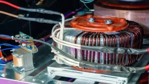
Every transformer experiences energy losses during operation—and understanding these losses is essential for improving performance. Among them, copper loss is one of the most significant types, occurring in the windings due to electrical resistance.
When current flows through the transformer coils, heat is generated as a byproduct of resistance. This heat not only reduces the transformer’s efficiency but also puts stress on its insulation and components, potentially shortening its lifespan over time.

As the demand for energy-efficient systems grows, minimizing copper losses becomes a top priority. Whether you’re designing new equipment or maintaining existing infrastructure, reducing copper losses can lead to lower energy costs, enhanced reliability, and better sustainability in modern power systems.
What Are Copper Losses?

Copper losses—also known as I²R losses—occur in a transformer’s windings whenever it carries electrical load. These losses happen because current flowing through the coils encounters resistance, and according to Joule’s law, this results in heat generation.
Copper losses are load-dependent, meaning they only occur when the transformer is delivering power to a connected load. The more current that flows through the windings, the more heat is produced—and the greater the energy lost in the form of heat.
Both primary and secondary windings contribute to copper losses. The total copper loss can be calculated using the formula:
P = I²R,
where I is the current and R is the resistance of the winding.
Unlike core (iron) losses that are present even at no load, copper losses occur only under load conditions, and they increase rapidly as current increases. That’s why reducing copper losses is crucial for maintaining transformer efficiency during high-demand operation.
Why Do Copper Losses Occur?

Copper losses in a transformer happen due to a combination of physical and electrical factors related to the winding design, material, and how the transformer operates. Let’s break down the main causes:
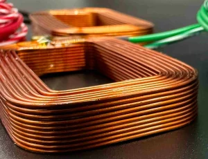
Ohmic Resistance in Windings
Every conductor has resistance—even high-conductivity materials like copper. When current flows through these windings, resistance turns part of the energy into heat.Current Magnitude (I² Relationship)
Losses grow exponentially with current. According to the formula P = I²R, doubling the current leads to four times the copper loss. That’s why high-load conditions see more severe losses.Winding Geometry & Coil Layers
More coil layers or longer wire paths increase total resistance. Poor winding layout can make heat dissipation worse, further increasing resistive losses.Temperature Effects
As temperature rises, the resistance of copper also increases. That means transformers operating at higher temperatures experience greater copper losses, creating a compounding heat effect.Switching Frequency & Skin Effect
In high-frequency transformers, current tends to flow near the conductor’s surface (the skin effect), effectively reducing cross-sectional area and increasing resistance.Harmonics & Proximity Effect
Harmonic currents (caused by non-linear loads) and proximity effects (interaction between nearby conductors) can increase localized resistance and losses.
Understanding these causes is the first step toward reducing copper losses and designing more efficient, long-lasting transformers.
Formula and Measurement

To calculate copper losses in a transformer, we use a simple but powerful formula based on Joule’s Law:
P = I² × R
Where:
P = power loss (watts)
I = current through the winding (amps)
R = resistance of the winding (ohms)
For a transformer with both primary and secondary windings, the total copper loss is:
Pc = Ip² × Rp + Is² × Rs
Where:
Ip and Is = current in the primary and secondary windings
Rp and Rs = resistance of the primary and secondary windings
This formula shows that even a small increase in current causes a sharp rise in power loss, since the current is squared. That’s why heavy load conditions demand extra attention.
To measure copper losses, engineers often perform a short-circuit test, where the secondary is shorted and a reduced voltage is applied to the primary to measure current and losses under load conditions.
By applying this formula and test, we can evaluate, predict, and optimize a transformer’s load performance efficiently.
Impact on Transformer Efficiency

Copper losses directly reduce a transformer’s energy efficiency, as a portion of the input power is converted into heat instead of useful output. Since these losses grow with the square of the load current, they become especially significant during high-load operation.
The heat generated by copper losses raises the transformer’s operating temperature, requiring robust cooling systems to prevent overheating. If not managed properly, this thermal stress can weaken insulation materials, leading to a decline in performance and even premature failure.
Over time, the stress from fluctuating temperatures and excessive current contributes to a shorter lifespan and reduced reliability. Additionally, wasted energy translates into higher operating costs, particularly in continuous-use or industrial settings.
Minimizing copper losses isn’t just about boosting efficiency—it’s about improving system durability, safety, and economic performance across the transformer’s lifecycle.
How to Reduce Copper Losses

Reducing copper losses is crucial for boosting transformer efficiency, longevity, and cost-effectiveness. Let’s look at two approaches: design and operation.
Design Strategies
Use larger conductor cross-sections: This lowers resistance and helps dissipate heat more efficiently.
Choose high-conductivity materials: Materials like pure copper or copper foil offer lower resistivity, cutting down I²R losses.
Optimize winding layout: A layout that ensures uniform current distribution minimizes localized heating and skin effect issues.
Operational Strategies
Avoid over- or under-loading: Transformers perform best near their rated load; extremes increase losses.
Use efficient cooling systems: Cooling helps stabilize resistance by maintaining lower winding temperatures.
Apply harmonic filters or low-THD equipment: Harmonics can exacerbate copper losses—filtering them protects performance.
Together, these strategies offer a balanced approach to minimizing energy loss and maximizing transformer performance.
Copper Loss vs Iron Loss

To fully understand transformer efficiency, it helps to compare copper loss with iron loss—the two main types of transformer losses. Here’s how they differ:
Trends in Reducing Losses

As transformer technology evolves, manufacturers and engineers are adopting smarter ways to reduce energy loss, especially copper losses. Here are some of the latest trends making a difference:
Amorphous metal cores + low-resistance windings: This combo helps tackle both copper and iron losses simultaneously, offering high efficiency especially in distribution transformers.
Digital simulation tools: Software-driven hotspot analysis and thermal modeling allow precise prediction of where losses and overheating may occur—leading to better winding and cooling designs.
Smart grid load balancing: With the help of real-time data and AI, smart grids optimize transformer loading, preventing overloads that spike copper loss.
Litz wire in high-frequency transformers: Used in EV chargers, UPS, and medical devices, Litz wire reduces skin effect and proximity effect, minimizing copper loss in high-frequency applications.
These innovations reflect the industry’s push for energy-efficient, reliable, and eco-conscious power infrastructure.
FAQs
1. Are copper losses constant?
No. They are load-dependent and increase with the square of the current.
2. Do aluminum windings have higher copper losses?
Yes. Aluminum has higher electrical resistance than copper, leading to greater losses.
3. Can copper losses be eliminated?
Not entirely, but they can be minimized with smart design and proper load management.

One Response
Thank you for sharing this insightful article! I found the information really useful and thought-provoking. Your writing style is engaging, and it made the topic much easier to understand. Looking forward to reading more of your posts!