


Every transformer experiences energy losses during operation, and understanding these losses is essential to improving efficiency and performance. One of the most significant is Kupferverlust, which occurs in the Transformatorwicklungen due to the electrical resistance of the winding conductors.
When current flows through Transformatorwicklungen, electrical resistance generates heat, resulting in Kupferverlust. This heat reduces transformer efficiency and places additional stress on the insulation and other components, potentially shortening the transformer’s service life over time.

Da die Nachfrage nach energieeffiziente Systeme continues to grow, reducing transformer copper losses has become increasingly important. Whether designing new equipment or maintaining existing infrastructure, minimizing these losses can help lower energy costs, improve Zuverlässigkeit, and support Nachhaltigkeit in modern Energiesysteme.
Was sind Kupferverluste?
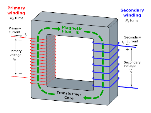
Kupferverluste, also known as I²R-Verluste, occur in a Transformatorwicklungen when current flows through them under load. As the current encounters electrical resistance in the winding conductors, heat is generated in accordance with Joule’s law.
Unlike no-load losses, copper losses depend on the load current. As the current flowing through the windings increases, more heat is generated and more electrical energy is dissipated as heat.
Both the Primär- und Sekundärwicklungen contribute to transformer copper losses. The total copper loss is calculated using the following formula:
P = I²R
where I represents the current and R represents the winding resistance.
Im Gegensatz zu core (iron) losses, which occur even when the transformer is operating without a load, copper losses depend on the load current. As current increases, copper losses rise in proportion to the square of the current. Therefore, minimizing copper losses is essential for maintaining transformer efficiency, particularly under high-load conditions.
Warum kommt es zu Kupferverlusten?

Copper losses in transformers result from several physical and electrical factors related to Wicklungsausführung, conductor materials, and operating conditions. The main causes include:
Ohmscher Widerstand in Wicklungen
All conductors have electrical resistance, including highly conductive materials such as Kupfer. As current flows through the windings, this resistance converts part of the electrical energy into heat.Stromstärke (I²-Verhältnis)
Copper losses increase with the square of the current, as described by the formula P = I²R. Doubling the current increases copper losses fourfold, making them significantly higher under heavy-load conditions.Wicklungsgeometrie und Spulenlagen
Additional coil layers and longer wire paths increase the total winding resistance. An inefficient winding layout can also hinder heat dissipation, further increasing Kupferverluste.Temperatureffekte
As temperature increases, the electrical resistance of copper rises. Transformers operating at higher temperatures therefore experience greater Kupferverluste, which can contribute to further heat generation.Schaltfrequenz und Skin-Effekt
In high-frequency transformers, the Hauteffekt causes current to concentrate near the conductor’s surface. This reduces the effective cross-sectional area available for current flow, increasing AC resistance and associated losses.Obertöne und Nahbesprechungseffekt
Harmonic currents, often associated with non-linear loads, and the Näherungseffekt, caused by interactions between nearby conductors, can increase effective winding resistance and contribute to additional losses.
Understanding these factors is an important first step toward reducing transformer copper losses and designing more efficient, durable transformers.
Formel und Messung

Berechnen Kupferverluste In einem Transformator verwenden wir eine einfache, aber leistungsstarke Formel basierend auf Joules Gesetz:
P = I² × R
Wo:
P = Leistungsverlust (Watt)
ICH = Strom durch die Wicklung (Ampere)
R = Widerstand der Wicklung (Ohm)
Für einen Transformator mit beiden Primär- und Sekundärwicklungenbeträgt der gesamte Kupferverlust:
Pc = Ip² × Rp + Is² × Rs
Wo:
IP Und Ist = Strom in der Primär- und Sekundärwicklung
Rp Und Rs = Widerstand der Primär- und Sekundärwicklung
Diese Formel zeigt, dass Schon eine kleine Stromerhöhung führt zu einem starken Anstieg der Verlustleistung, da der Strom quadriert ist. Deshalb erfordern hohe Lastbedingungen besondere Aufmerksamkeit.
Zu Kupferverluste messenführen Ingenieure oft eine Kurzschlussprüfung, wobei die Sekundärseite kurzgeschlossen ist und ein reduzierter Stromspannung wird auf die Primärseite angewendet, um Strom und Verluste unter Lastbedingungen zu messen.
Durch die Anwendung dieser Formel und dieses Tests können wir die Lastleistung eines Transformators effizient bewerten, vorhersagen und optimieren.
Auswirkungen auf die Transformatoreffizienz

Transformator Kupfer Verluste reduce energy efficiency by converting part of the input power into heat rather than useful output. Because these losses increase with the square of the load current, they become particularly significant under heavy-load conditions.
Heat generated by Kupferverluste increases the transformer’s operating temperature, making effective cooling essential to prevent overheating. Without proper Wärmemanagement, prolonged heat exposure can degrade Wicklungsisolation, reduzieren transformer performance, and potentially lead to premature failure.
Over time, temperature fluctuations and excessive current can shorten a transformer’s service life and reduce its reliability. Energy wasted through Kupferverluste also increases Betriebskosten, particularly in industrial applications where transformers run continuously.
Reducing copper losses is not only about improving transformer efficiency but also about enhancing equipment durability, maintaining safety, and lowering costs throughout the transformer’s service life.
So reduzieren Sie Kupferverluste

Reducing Kupferverluste is essential for improving transformer efficiency, extending service life, and lowering operating costs. Two key approaches are Transformatordesign and operational management.
Designstrategien
Increase conductor cross-sectional area: Larger conductors reduce electrical resistance and help dissipate heat.
Select high-conductivity materials: Materials such as reines Kupfer Und Kupferfolie have low resistivity, helping reduce I²R losses.
Wicklungslayout optimieren: A well-designed winding layout promotes gleichmäßige Stromverteilung, helping limit localized heating and skin effect issues.
Betriebsstrategien
Avoid overloading or underloading: Transformers are designed to operate within their rated load range, while operating outside this range can increase losses.
Maintain effective cooling: Cooling systems help keep winding temperatures under control, limiting increases in elektrischer Widerstand.
Use harmonic filters or low-THD equipment: Harmonic currents can increase copper losses, so filtering harmonics helps reduce their impact on transformer performance.
Together, these design and operational measures provide a practical approach to reducing transformer copper losses, minimizing energy waste, and maintaining efficient operation.
Kupferverlust vs. Eisenverlust
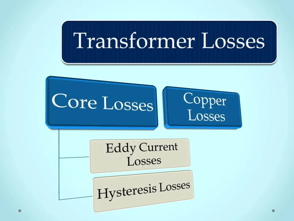
To better understand transformer efficiency, it is important to distinguish between Kupferverluste Und Eisenverluste, the two main types of transformer losses. Their key differences are outlined below.
Trends bei der Verlustreduzierung

Als Transformatortechnologie entwickelt sich weiter, manufacturers and engineers are adopting more effective approaches to reducing Energieverluste, insbesondere Kupferverluste. Key trends include:
Amorphe Metallkerne + Wicklungen mit geringem Widerstand: Combining these technologies helps reduce both copper losses and iron losses, improving efficiency, particularly in distribution transformers.
Digitale Simulationstools: Software-based Hotspot-Analyse and thermal modeling help predict where losses and overheating may occur, supporting better winding and cooling designs.
Intelligenter Netzlastausgleich: With real-time data and AI, smart grids optimize transformer loading, preventing overloads that can sharply increase Kupferverluste.
Litzendraht in Hochfrequenztransformatoren: Used in EV chargers, UPS systems, Und Medizinprodukte, Litze helps reduce the skin effect and proximity effect, minimizing Kupferverluste in high-frequency applications.
These developments reflect the industry’s ongoing focus on improving Energieeffizienz, reliability, and environmental sustainability across power infrastructure.
FAQs
1. Sind die Kupferverluste konstant?
No. Kupferverluste depend on the load and increase with the square of the current.
2. Haben Aluminiumwicklungen höhere Kupferverluste?
Ja. Aluminium hat höherer elektrischer Widerstand than copper, which can result in greater winding losses under the same current conditions.
3. Können Kupferverluste vermieden werden?
No. They cannot be eliminated entirely, but they can be minimiert through thoughtful transformer design and proper load management.


 German
 English
 Spanish
 Russian
 Italian
 Chinese
Eine Antwort
Vielen Dank, dass Sie diesen aufschlussreichen Artikel mit uns geteilt haben! Ich fand die Informationen wirklich nützlich und zum Nachdenken anregend. Ihr Schreibstil ist ansprechend und hat das Thema viel leichter verständlich gemacht. Ich freue mich darauf, mehr von Ihren Beiträgen zu lesen!