


Für high-frequency transformers, especially those operating above 50 kHz, die Art und Weise, wie Sie die Wicklungen gestalten plays a critical role in overall performance. At higher frequencies, conventional design approaches become less effective because the Transformatorwicklung layout directly influences power losses, heat generation, electromagnetic interference, and overall efficiency.
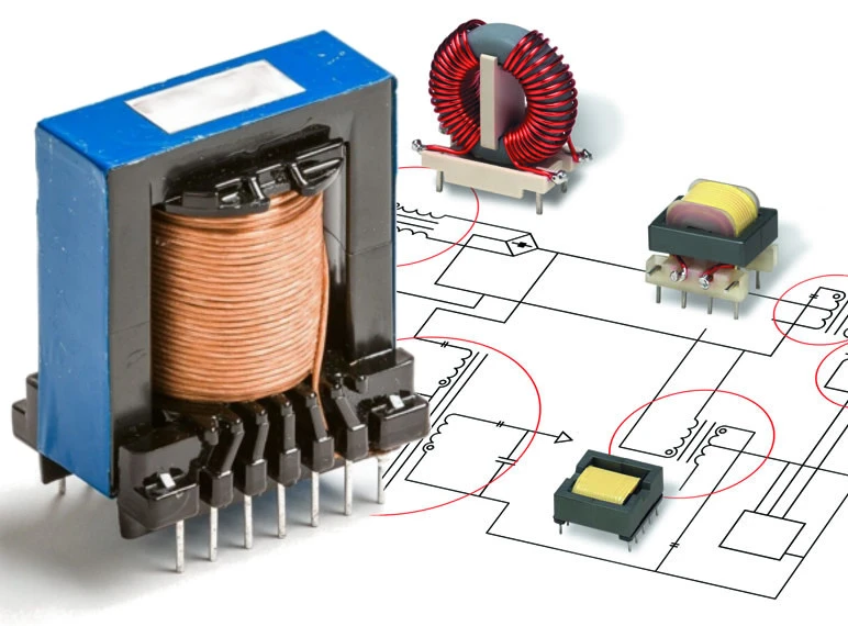
Wirksam Transformatorwicklung design helps reduce Wechselstromwiderstand, control Haut- und Näheeffekte, minimize Streuinduktivitätund halten Elektromagnetische Interferenz (EMI) within acceptable limits. Whether the application involves a compact SMPS or a custom power module, properly designed Transformatorwicklungen are essential for reliable performance, long service life, and compliance with electrical requirements.
In this article, we’ll cover the key winding considerations for high-frequency Transformer, using practical design principles and clear explanations to help engineers better understand the factors that affect efficiency and performance.
Haut- und Näheeffekte
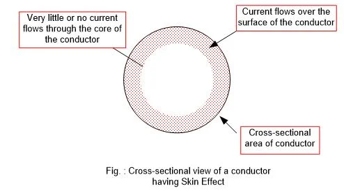
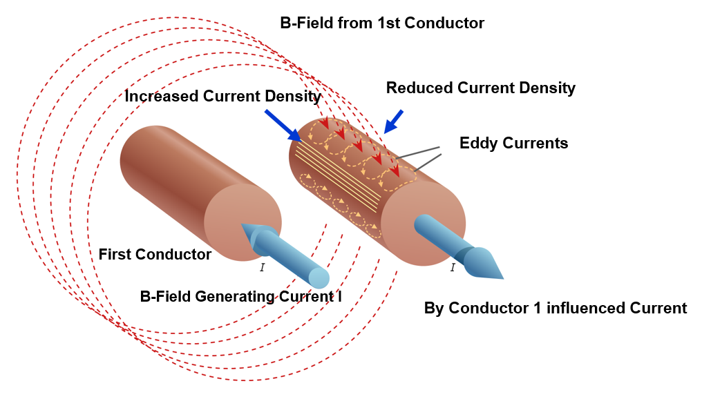
At high frequencies, current no longer flows evenly through the conductor. Instead, it becomes concentrated near the wire surface, a phenomenon known as the Hauteffekt. As frequency rises, the effective current-carrying area decreases, increasing Wechselstromwiderstand and generating more heat within the Transformatorwicklung.
Next comes the Näherungseffekt. When conductors are positioned close together, their magnetic fields alter the current distribution and force it into narrower paths. This further increases Wechselstromwiderstand and reduces Transformatorwicklung Effizienz.
Combined with the skin effect, the proximity effect becomes a major source of winding loss in high-frequency transformers. For this reason, selecting the right wire type and winding layout is essential for reducing losses and improving overall performance.
Auswahl von Drahttyp und -größe

Auswahl des richtigen Kabeltyps is essential for reducing losses in high-frequency Transformatorwicklungen.
Zu den verfügbaren Optionen gehören Litze is widely used because it consists of many thin, individually insulated strands woven together to distribute current more evenly. This design helps reduce both Haut Und Näherungseffekte, making it especially effective in high-frequency applications up to about 1 MHz.
However, Litze has practical limits. Above about 1 MHz, strand diameter becomes increasingly important. To remain effective, each strand should generally be weniger als die doppelte Skintiefe at the target operating frequency.
For very high frequencies or higher-current Transformatorwicklung applications, alternatives such as Folienwicklungen, Rohrleiter, Und Roebelkabel may provide better current handling while improving magnetic field distribution and thermal performance.
Ultimately, the best conductor depends on the operating frequency, current level, and winding geometry, but the goal remains the same: reduce losses and improve the efficiency of Transformatorwicklungen.
Wicklungstopologien zur Reduzierung von Verlusten
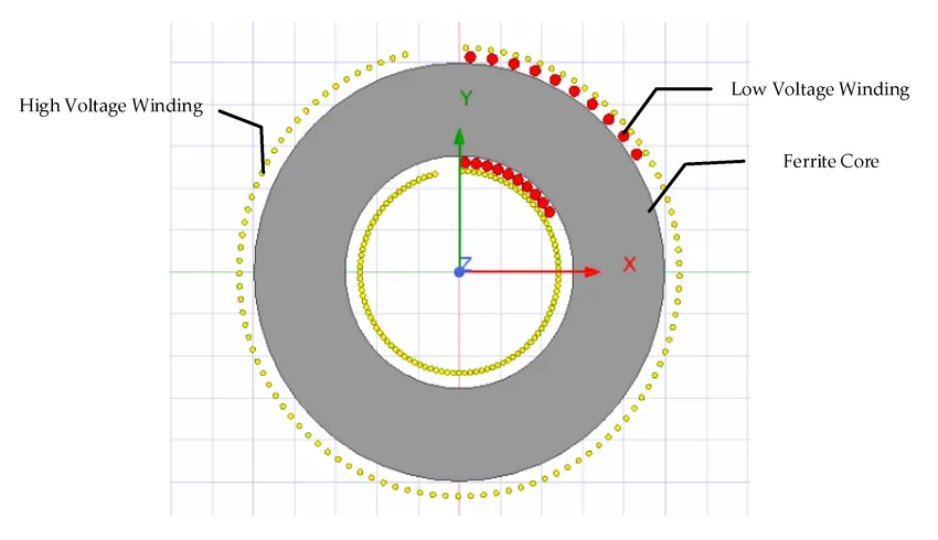
The arrangement of Transformatorwicklungen has a significant impact on overall performance. An optimized winding layout can help reduce Wechselstromwiderstand, Grenze parasitic effects, and improve heat management.
Zum Beispiel, paralleled and interleaved windings distribute current more evenly and help reduce the proximity effect. By alternating primary and secondary winding layers, magnetic coupling is improved, which can lower losses and increase efficiency.
Korb- (oder Streu-) Wicklung separates conductors rather than placing them closely side by side. This layout helps reduce parasitic capacitance and proximity-effect losses, making it useful in high-frequency Transformatorwicklung designs.
Similarly, sandwich and helical structures can improve current distribution and maintain a more balanced magnetic field. This helps reduce leakage flux and improve the efficiency of Transformatorwicklungen.
Each winding layout involves trade-offs, but a well-designed topology can significantly reduce electrical losses and improve overall transformer performance.
Umgang mit Parasiten und Leckagen
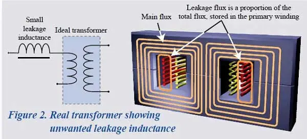
High-frequency transformers commonly face two winding-related challenges: Streuinduktivität Und parasitäre Kapazität. If not properly controlled, both can reduce the performance and efficiency of Transformatorwicklungen.
Streuinduktivität occurs when part of the magnetic flux does not link the primary and secondary windings. While some designs use it intentionally, excessive leakage inductance can slow switching performance and create voltage spikes. Techniques such as interleaved windings Und Leckageschichten can help balance magnetic coupling, insulation, and overall Transformatorwicklung Leistung.
Parasitäre Kapazität develops between closely spaced winding layers and can contribute to Selbstresonanz and EMI problems in high-frequency transformers. Using sorgfältiger Schichtabstand, suitable insulation, and Korbwickelmuster can help reduce this unwanted effect.
Managing these parasitic effects requires a balanced Transformatorwicklung design that limits electrical losses and interference without compromising efficiency, insulation performance, or safety.
Isolierung und Füllfaktor

A well-designed Transformatorwicklung layout must balance electrical performance, available space, and safety. The Füllfaktor indicates how efficiently the wire occupies the winding window, with higher values allowing more conductor to fit within the same space.
In comparison, orthozyklische Wicklung arranges wires in a uniform pattern and can achieve a fill factor of up to 90%, während zufällige Wicklung typically reaches around 75%. A higher fill factor generally means more copper and less unused space, helping improve the efficiency and compactness of Transformatorwicklungen.
As winding density increases, Isolierung becomes even more important. Proper Schichtisolierung Und dielektrischer Abstand are essential for preventing short circuits, particularly in high-voltage Transformatorwicklung designs. The choice of insulation material, thickness, and placement all affect long-term safety and reliability.
A well-designed Transformatorwicklung should therefore balance high copper utilization with effective insulation, helping maintain both electrical performance and dependable protection.
Thermische und mechanische Einschränkungen
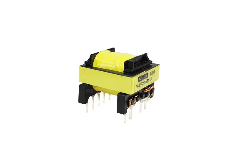 High-frequency transformers can generate significant heat, especially when Stromdichte becomes too high. To reduce the risk of overheating, current density should generally remain within a safe range of about 4–10 A/mm², depending on the cooling method and overall Transformatorwicklung Design.
In addition, effective Kühlung through airflow, heatsinks, or proper spacing helps control winding temperature, maintain stable performance, and extend the service life of high-frequency Transformatorwicklungen.
Mechanical stability is equally important for reliable Transformatorwicklung performance. Windings must withstand Vibration, Wärmeausdehnung, Und Umgang mit Stress during operation and assembly. If the windings become loose or shift over time, insulation damage and changes in electrical performance may occur.
For this reason, a robust mechanical design helps keep Transformatorwicklungen securely in place, supporting consistent efficiency, long-term reliability, and stable operation under real-world conditions.
Integration in den Design-Workflow
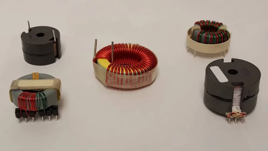
Wirksam Transformatorwicklung design is an iterativer Prozess, since each design decision can influence the next. Careful planning is therefore essential for balancing electrical performance, efficiency, and manufacturability.
The process typically begins with Kernauswahl based on operating frequency and power requirements, followed by calculating the appropriate Rundenzahl for voltage and magnetic flux. Next, the Wicklungsgeometrie is refined to balance efficiency, available space, and cooling. Finally, parasitic effects such as leakage inductance and capacitance should be evaluated to ensure stable and reliable Transformatorwicklung Leistung.
For better results, Finite-Elemente-Analyse (FEM) tools can be used to evaluate Wechselstromwiderstand, Stromdichte, magnetische Feldverteilung, and other key parameters. This helps identify potential Transformatorwicklung issues before moving to the prototype stage.
In practice, effective Transformatorwicklung design combines engineering analysis with practical experience. Integrating these steps early can reduce development time, lower costs, and minimize troubleshooting later.
Fortgeschrittene Praktiken und neue Trends
As high-frequency applications continue to advance, Transformatorwicklung techniques are also evolving, with new conductor designs and winding layouts helping improve efficiency and power density.
One example is Roebelkabel, which use transposed strands to reduce AC-Verluste in strong parallel magnetic fields. This makes them well suited for high-current or compact Transformatorwicklung applications where efficient current distribution is essential.
Spiral- und Verbundfolienwicklungen are also becoming more common in advanced Transformatorwicklung designs. These structures help improve magnetic field uniformity, reduce hotspots, and support more consistent performance at higher operating frequencies.
Another important consideration is zirkulierende Ströme in parallel strands, which can create additional heat and current imbalance. Proper strand transposition and spacing can help reduce these unwanted effects.
Although these techniques are not required for every design, they can provide clear benefits in efficiency, thermal stability, and EMI control for demanding high-frequency Transformatorwicklungen.
Abschluss
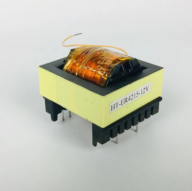
High-frequency transformer performance depends greatly on effective Transformatorwicklung design. From conductor selection and winding geometry to parasitic effects, each factor can influence efficiency, thermal behavior, and long-term reliability. Applying the right design principles helps reduce losses and maintain stable transformer performance.
For support with your Transformatorwicklung Design, Kontaktieren Sie unser Team for expert guidance, custom solutions, and simulation insights tailored to your specific application.
Häufig gestellte Fragen zur Wicklung von Hochfrequenztransformatoren
1. Was ist der ideale Frequenzbereich für die Verwendung von Litzendraht?
Litze is generally most effective between 10 kHz and 1 MHz, where skin and proximity effects become more significant. Above 1 MHz, strand diameter and construction must be carefully optimized to control AC losses in high-frequency Transformatorwicklungen.
2. Wie berechne ich die Windungszahl eines Hochfrequenztransformators?
A common starting formula for high-frequency Transformatorwicklung design is:
Umdrehungen = (Vin × 10⁸) / (4 × Bmax × Ac × f)
where Vin is the input voltage, Bmax is the maximum flux density, Ac is the core area, and f is the operating frequency. The final turn count may need adjustment for voltage drop and regulation requirements.
3. Kann ich für Niedrigleistungsdesigns Standardkabel anstelle von Litzen verwenden?
Yes. For low-current applications operating at relatively low frequencies, standard magnet wire may be suitable for Transformatorwicklungen. However, as frequency rises above roughly 100–200 kHz, increasing AC losses should be considered when selecting the conductor.

 German
 English
 Spanish
 Russian
 Italian
 Chinese
Eine Antwort
Vielen Dank, dass Sie diesen aufschlussreichen Artikel mit uns geteilt haben! Ich fand die Informationen wirklich nützlich und zum Nachdenken anregend. Ihr Schreibstil ist ansprechend und hat das Thema viel leichter verständlich gemacht. Ich freue mich darauf, mehr von Ihren Beiträgen zu lesen!