


為了 high-frequency transformers, especially those operating above 50 kHz, 設計繞組的方式 plays a critical role in overall performance. At higher frequencies, conventional design approaches become less effective because the 變壓器繞組 layout directly influences power losses, heat generation, electromagnetic interference, and overall efficiency.
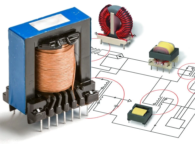
有效的 變壓器繞組 design helps reduce 交流電阻, control 趨膚效應和鄰近效應, minimize 漏電感,並保持 電磁幹擾 (EMI) within acceptable limits. Whether the application involves a compact SMPS or a custom power module, properly designed transformer windings are essential for reliable performance, long service life, and compliance with electrical requirements.
In this article, we’ll cover the key winding considerations for high-frequency 變壓器, using practical design principles and clear explanations to help engineers better understand the factors that affect efficiency and performance.
趨膚效應和鄰近效應
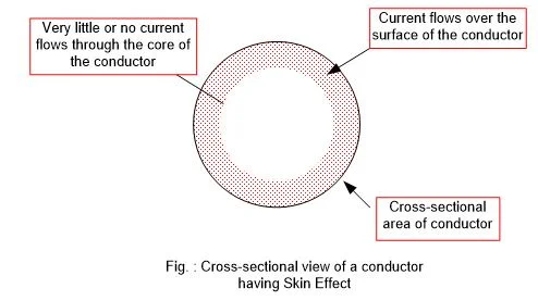
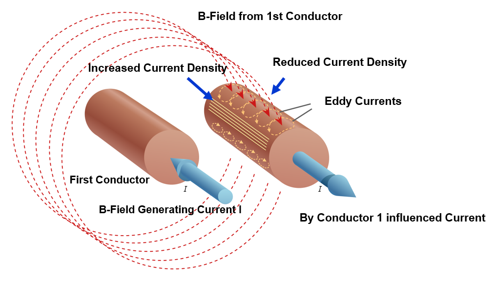
At high frequencies, current no longer flows evenly through the conductor. Instead, it becomes concentrated near the wire surface, a phenomenon known as the 趨膚效應. As frequency rises, the effective current-carrying area decreases, increasing 交流電阻 and generating more heat within the 變壓器繞組.
Next comes the 鄰近效應. When conductors are positioned close together, their magnetic fields alter the current distribution and force it into narrower paths. This further increases 交流電阻 and reduces 變壓器繞組 效率。
Combined with the skin effect, the proximity effect becomes a major source of winding loss in high-frequency transformers. For this reason, selecting the right wire type and winding layout is essential for reducing losses and improving overall performance.
電線類型和尺寸選擇

選擇正確的電線類型 is essential for reducing losses in high-frequency transformer windings.
Among the available options, 利茲線 is widely used because it consists of many thin, individually insulated strands woven together to distribute current more evenly. This design helps reduce both 皮膚 和 鄰近效應, making it especially effective in high-frequency applications up to about 1 MHz.
However, 利茲線 has practical limits. Above about 1 MHz, strand diameter becomes increasingly important. To remain effective, each strand should generally be 小於集膚深度的兩倍 at the target operating frequency.
For very high frequencies or higher-current 變壓器繞組 applications, alternatives such as 箔式繞組, 管狀導體, 和 羅貝爾電纜 may provide better current handling while improving magnetic field distribution and thermal performance.
Ultimately, the best conductor depends on the operating frequency, current level, and winding geometry, but the goal remains the same: reduce losses and improve the efficiency of transformer windings.
減少損耗的繞組拓樸結構
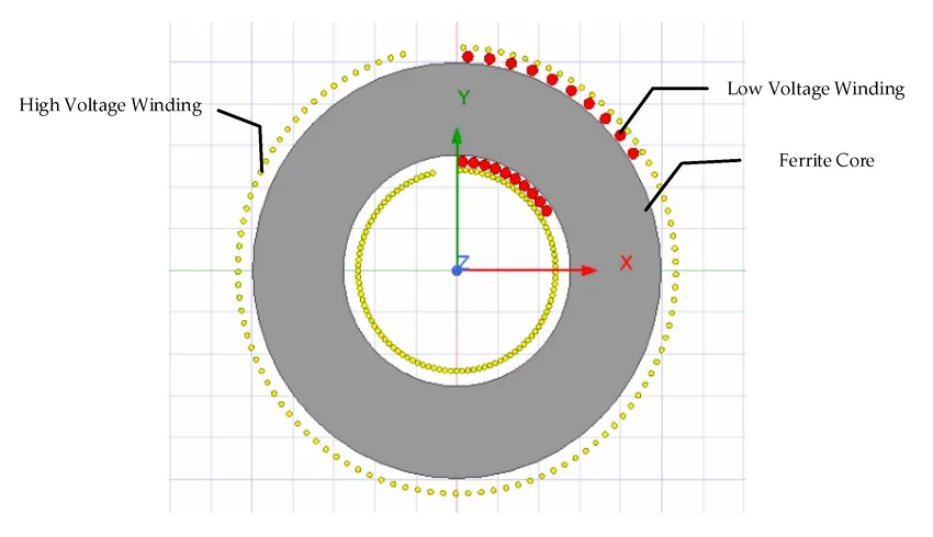
The arrangement of transformer windings has a significant impact on overall performance. An optimized winding layout can help reduce 交流電阻, 限制 parasitic effects, and improve heat management.
For example, paralleled and interleaved windings distribute current more evenly and help reduce the proximity effect. By alternating primary and secondary winding layers, magnetic coupling is improved, which can lower losses and increase efficiency.
籃式(或散式)繞線 separates conductors rather than placing them closely side by side. This layout helps reduce parasitic capacitance and proximity-effect losses, making it useful in high-frequency 變壓器繞組 designs.
Similarly, sandwich and helical structures can improve current distribution and maintain a more balanced magnetic field. This helps reduce leakage flux and improve the efficiency of transformer windings.
Each winding layout involves trade-offs, but a well-designed topology can significantly reduce electrical losses and improve overall transformer performance.
管理寄生效應和洩漏
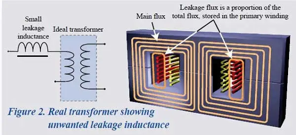
High-frequency transformers commonly face two winding-related challenges: 漏電感 和 寄生電容. If not properly controlled, both can reduce the performance and efficiency of transformer windings.
漏電感 occurs when part of the magnetic flux does not link the primary and secondary windings. While some designs use it intentionally, excessive leakage inductance can slow switching performance and create voltage spikes. Techniques such as interleaved windings 和 洩漏層 can help balance magnetic coupling, insulation, and overall 變壓器繞組 表現。
寄生電容 develops between closely spaced winding layers and can contribute to 自諧振 and EMI problems in high-frequency transformers. Using 仔細的層間距, suitable insulation, and 籃子纏繞圖案 can help reduce this unwanted effect.
Managing these parasitic effects requires a balanced 變壓器繞組 design that limits electrical losses and interference without compromising efficiency, insulation performance, or safety.
絕緣和填充係數

A well-designed 變壓器繞組 layout must balance electrical performance, available space, and safety. The 填充因子 indicates how efficiently the wire occupies the winding window, with higher values allowing more conductor to fit within the same space.
In comparison, 正交環繞制 arranges wires in a uniform pattern and can achieve a fill factor of up to 90%, 儘管 隨機纏繞 typically reaches around 75%. A higher fill factor generally means more copper and less unused space, helping improve the efficiency and compactness of transformer windings.
As winding density increases, 絕緣 becomes even more important. Proper 層絕緣層 和 介電間距 are essential for preventing short circuits, particularly in high-voltage 變壓器繞組 designs. The choice of insulation material, thickness, and placement all affect long-term safety and reliability.
A well-designed 變壓器繞組 should therefore balance high copper utilization with effective insulation, helping maintain both electrical performance and dependable protection.
熱和機械約束
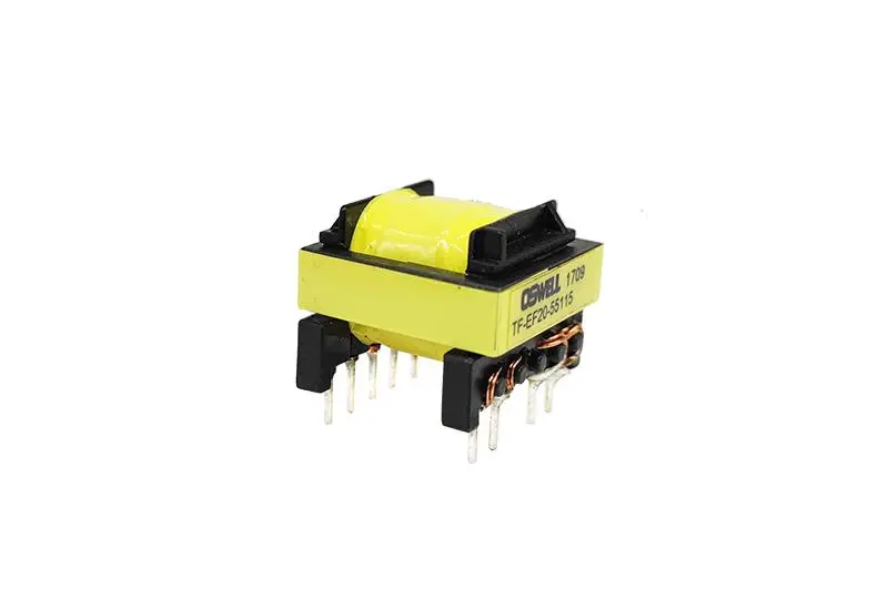 High-frequency transformers can generate significant heat, especially when 電流密度 becomes too high. To reduce the risk of overheating, current density should generally remain within a safe range of about 4–10 安/平方毫米, depending on the cooling method and overall 變壓器繞組 設計。
In addition, effective 冷卻 through airflow, heatsinks, or proper spacing helps control winding temperature, maintain stable performance, and extend the service life of high-frequency transformer windings.
Mechanical stability is equally important for reliable 變壓器繞組 performance. Windings must withstand 振動, 熱膨脹, 和 處理壓力 during operation and assembly. If the windings become loose or shift over time, insulation damage and changes in electrical performance may occur.
For this reason, a robust mechanical design helps keep transformer windings securely in place, supporting consistent efficiency, long-term reliability, and stable operation under real-world conditions.
整合到設計工作流程中
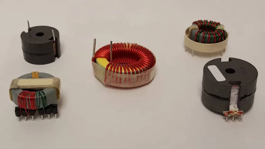
有效的 變壓器繞組 design is an 迭代過程, since each design decision can influence the next. Careful planning is therefore essential for balancing electrical performance, efficiency, and manufacturability.
The process typically begins with 核心選擇 based on operating frequency and power requirements, followed by calculating the appropriate 回合數 for voltage and magnetic flux. Next, the 繞組幾何形狀 is refined to balance efficiency, available space, and cooling. Finally, parasitic effects such as leakage inductance and capacitance should be evaluated to ensure stable and reliable 變壓器繞組 表現。
For better results, 有限元素分析(FEM) tools can be used to evaluate 交流電阻, 電流密度, 磁場分佈, and other key parameters. This helps identify potential 變壓器繞組 issues before moving to the prototype stage.
In practice, effective 變壓器繞組 design combines engineering analysis with practical experience. Integrating these steps early can reduce development time, lower costs, and minimize troubleshooting later.
先進實踐與新興趨勢
As high-frequency applications continue to advance, 變壓器繞組 techniques are also evolving, with new conductor designs and winding layouts helping improve efficiency and power density.
One example is 羅貝爾電纜, which use transposed strands to reduce 交流損耗 in strong parallel magnetic fields. This makes them well suited for high-current or compact 變壓器繞組 applications where efficient current distribution is essential.
螺旋和複合箔繞組 are also becoming more common in advanced 變壓器繞組 designs. These structures help improve magnetic field uniformity, reduce hotspots, and support more consistent performance at higher operating frequencies.
Another important consideration is 環流 in parallel strands, which can create additional heat and current imbalance. Proper strand transposition and spacing can help reduce these unwanted effects.
Although these techniques are not required for every design, they can provide clear benefits in efficiency, thermal stability, and EMI control for demanding high-frequency transformer windings.
結論
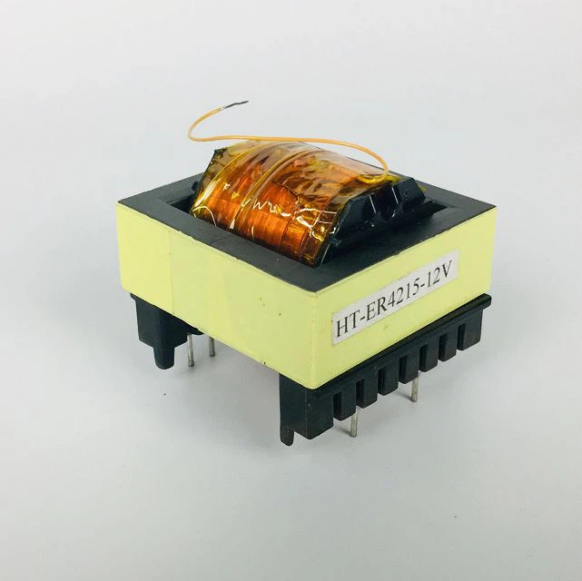
High-frequency transformer performance depends greatly on effective 變壓器繞組 design. From conductor selection and winding geometry to parasitic effects, each factor can influence efficiency, thermal behavior, and long-term reliability. Applying the right design principles helps reduce losses and maintain stable transformer performance.
For support with your 變壓器繞組 設計, 聯絡我們的團隊 for expert guidance, custom solutions, and simulation insights tailored to your specific application.
高頻變壓器繞製常見問題解答
1. 使用利茲線的理想頻率範圍是多少?
利茲線 is generally most effective between 10 kHz and 1 MHz, where skin and proximity effects become more significant. Above 1 MHz, strand diameter and construction must be carefully optimized to control AC losses in high-frequency transformer windings.
2.如何計算高頻變壓器的匝數?
A common starting formula for high-frequency 變壓器繞組 design is:
匝數 = (Vin × 10⁸) / (4 × Bmax × Ac × f)
where Vin is the input voltage, Bmax is the maximum flux density, Ac is the core area, and f is the operating frequency. The final turn count may need adjustment for voltage drop and regulation requirements.
3. 對於低功耗設計,我可以使用標準線來代替 Litz 線嗎?
Yes. For low-current applications operating at relatively low frequencies, standard magnet wire may be suitable for transformer windings. However, as frequency rises above roughly 100–200 kHz, increasing AC losses should be considered when selecting the conductor.

 Chinese
 English
 Spanish
 Russian
 Italian
 German
一則回覆
感謝您分享這篇富有洞察力的文章!我發現這些資訊非常實用,發人深省。您的寫作風格引人入勝,讓這個主題更容易理解。期待閱讀您更多文章!