Toroidal transformers stand out with their unique doughnut-shaped core, giving them excellent symmetry and magnetic efficiency. This closed-loop design reduces stray magnetic fields, lowers audible hum, and improves energy transfer compared to conventional laminated core transformers. The symmetry also means more uniform winding distribution, which helps control leakage and minimize electromagnetic interference.

You’ll find toroidal transformers in audio equipment, medical devices, and power supplies—applications where clean power, compact size, and quiet operation are critical. Good design matters here, because the right geometry, materials, and winding method directly affect efficiency, performance, and reliability.
Core Advantages & Design Benefits

Toroidal transformers are loved for their compact size, light weight, and high efficiency—often reaching 90–95%. Their ring-shaped core allows more copper in less space, improving performance without adding bulk. This makes them ideal for tight enclosures and portable systems.
Another advantage is their low audible hum and minimal stray magnetic field. This comes from the tight, even winding around a grain-oriented steel core, which helps contain magnetic flux and reduce interference—perfect for sensitive electronics like audio gear or medical instruments.
Core Geometry, Material & Dimension Fundamentals

The heart of a toroidal transformer is usually grain-oriented silicon steel, chosen for its low core loss and high magnetic permeability. Designers can adjust the diameter-to-height ratio for specific needs—larger diameters for lower profile builds, taller builds for higher power density.
For best efficiency, engineers aim for an optimal core ratio where copper losses are about 60% of iron losses. This balance maximizes energy transfer while keeping the transformer cool and reliable. Getting the geometry and material right from the start sets the foundation for a long-lasting, high-performance design.
Electrical Design Parameters & Calculations
![]()
Designing a toroidal transformer starts with the basics—Faraday’s Law. This tells us how many turns of wire we need to generate the desired voltage:
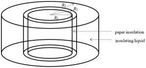
Next comes inductance, calculated using the core’s outer diameter (OD), inner diameter (ID), height, and material permeability. Choosing the right dimensions keeps the transformer efficient while minimizing losses.
Designers also look at the area product (Ap)—a key measure combining core size and winding space. Ap helps balance core size, surface area, and power density, while also factoring in thermal limits so the transformer runs cool and stable.
Winding Techniques & Leakage Control

Good winding design is just as important as good core design. A uniform distribution of windings around the toroid ensures minimal leakage inductance and electromagnetic interference (EMI). This even spread reduces stray fields and improves efficiency, especially in sensitive electronics.
In high-performance designs, winding may be done in carefully planned sections to control leakage for specific filtering effects. This method fine-tunes the transformer’s response, making it more stable and better suited to its intended application.
Advanced Design Optimization & Modeling

Modern toroidal transformer design benefits greatly from Finite Element Method (FEM) modeling. This simulation approach lets engineers visualize magnetic flux distribution, identify leakage paths, and evaluate how geometry changes affect performance—long before building a prototype.
Beyond modeling, designers can refine performance using automated design loops. By adjusting the fill factor (copper-to-window area), along with Y and Z geometric ratios, engineers can achieve the best balance of efficiency, mass, and heat management. These techniques, originally detailed in NASA design research, help produce transformers that are lighter, cooler, and more reliable.
High-Frequency and Application-Specific Considerations

For high-frequency designs, material selection is critical. Traditional grain-oriented steel works well for low-frequency power, but ferrite cores offer much lower losses for wide-band pulse and switching power supplies.
In applications like SMPS or GaN/SiC-based converters, designers must manage high-frequency leakage inductance and parasitic capacitance carefully. Excess capacitance can cause unwanted resonances, while poor leakage control can hurt efficiency. Balancing these factors requires precise winding layouts and, often, additional shielding or insulation techniques to maintain stable performance.
Practical Considerations & Design Trade-Offs

Designing a toroidal transformer isn’t just about theory—it’s about solving real-world build challenges. One common hurdle is winding complexity. Because the wire must pass repeatedly through the center of the core, winding can be slower and requires special tooling. Lead routing also demands careful planning to avoid excess strain or unwanted coupling between leads.
Another trade-off involves size versus efficiency. A slightly smaller core can save weight and material costs, but it may require thinner wire, which increases copper losses. In some designs—especially portable or aerospace applications—engineers accept this small efficiency drop for lighter, more compact transformers.
Tools and Resources for Designers

If you’re designing a toroidal transformer, a good set of tools and references will speed the process and improve accuracy. Classic design formulas from industry handbooks and NASA’s early toroid design software are still valuable starting points. Modern simulation programs can automate calculations for turns, flux density, and thermal performance, reducing trial-and-error.
For deeper learning, resources like the Transformer & Inductor Design Handbook and specialized manufacturer design guides provide proven methods and real-world tips. Combining these references with hands-on testing ensures your designs are both efficient and practical.
Ready to Bring Your Toroidal Transformer Design to Life?

Whether you need custom-engineered toroidal transformers, design optimization advice, or technical troubleshooting, our team is here to help. We combine industry expertise with precision engineering to deliver solutions that meet your performance, cost, and reliability goals.
Contact us today to discuss your project, request a quote, or get a professional design consultation. Let’s turn your transformer concept into a high-efficiency reality.
FAQs
How to design a toroidal transformer?
Start with Faraday’s Law to calculate EMF, then determine turns and power rating, operating frequency, and duty cycle. Use core dimensions and material data to size your transformer, keeping temperature rise in mind.
2. What are the disadvantages of toroidal transformers?
Toroidal transformers come with some trade-offs:
Higher cost due to complex manufacturing and premium materials
Limited power capacity, typically not suited for high-power applications over ~4 kW
Fragility, as cores can be brittle with low thermal expansion, making them more prone to damage
Higher inrush current, which can trigger fuses or damage components if not managed
3. Do toroidal transformers sound better?
Toroidal transformers can deliver cleaner sound with less hum and electrical noise, making them a popular choice in audio systems. Their tightly wound, closed-core design significantly reduces EMI and vibration. However, sound quality also depends on the overall system design and quality of components.
4. What is the most efficient transformer design?
Efficiency peaks when copper (winding) losses equal about 60% of iron (core) losses, a design principle especially true for toroidal transformers. Modern transformers often approach 98% or higher efficiency, particularly when using amorphous steel cores for lower core losses. The type genuinely most efficient depends on core materials, design balance, and operating conditions.