So, what is transformer winding? In simple terms, it’s the coils of wire—usually copper or aluminum—wrapped around a magnetic core inside a transformer. These windings are what make a transformer work. When alternating current (AC) flows through one coil, it creates a magnetic field that transfers energy to another coil. This process, called electromagnetic induction, allows the transformer to step voltage up or down depending on the need.

Whether you’re powering a home appliance or an entire factory, transformer winding plays a key role in delivering the right voltage safely and efficiently. It’s the heart of how electricity travels from one point to another.
Primary vs. Secondary Windings

Every transformer has two main sets of windings: the primary and the secondary.
The primary winding is the one connected to the input power source. When AC current flows through it, it creates a changing magnetic field in the transformer’s core. This field is what drives the whole process.
The secondary winding sits close to the primary and picks up that magnetic field. Through electromagnetic induction, it generates a new voltage that gets sent to the output load—like your appliances, tools, or equipment.
The number of turns in each winding determines whether the voltage is increased (step-up) or decreased (step-down). It’s a simple yet powerful system that keeps our electricity flowing exactly where and how we need it.
How Transformer Windings Work

To understand how transformer windings work, we need to look at a key principle in physics—Faraday’s Law of Electromagnetic Induction. It says that when the electric current in the primary winding changes, it creates a magnetic field that flows through the transformer’s core. This changing magnetic field induces a voltage in the secondary winding.
The amount of voltage in the secondary depends on the number of turns in each winding. This is called the turns ratio. For example, if the primary has 100 turns and the secondary has 50, the transformer will reduce the voltage by half—this is a step-down transformer. If the secondary has more turns than the primary, it steps the voltage up.
Here’s a simple rule:
Voltage ratio = Turns ratio
Current ratio = Inverse of the turns ratio
That’s the beauty of transformer winding—it changes voltage levels without any moving parts, using only smart physics.
Core and Windings Layout

The way transformer windings are arranged on the core plays a big role in how well the transformer works. Typically, windings are wrapped around a laminated iron core, which helps reduce something called eddy currents—tiny loops of wasted energy that can cause heat and power loss. Laminating the core helps keep the magnetic flow efficient and focused.
There are two main types of winding layouts: core-type and shell-type. In a core-type transformer, the windings surround the core. In a shell-type transformer, the core surrounds the windings. Each design affects how well the magnetic flux is coupled between the coils and how much leakage flux (unwanted magnetic field) escapes.
Choosing the right layout depends on the size, voltage level, and cooling needs of the transformer—but both layouts aim to make the most of the magnetic energy generated by the windings.
Basic Winding Types

Transformer windings can be arranged in different patterns, depending on the application, space, and cooling needs. Here are a few common types:
Helical Winding: A spiral-shaped winding, often used in high-current transformers. It’s simple, strong, and good for handling large currents.
Disc Winding: Made of flat coils stacked in layers like a sandwich. It allows better cooling and is great for medium to high-voltage transformers.
Sandwich Winding: Layers of primary and secondary windings are alternated. This design reduces leakage and improves magnetic coupling.
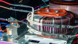
Toroidal Winding: Coils are wound in a ring shape around a toroidal (donut-shaped) core. These transformers are compact, efficient, and have very low electromagnetic interference.
Each winding type offers different advantages—some save space, others handle heat better, and some reduce energy losses. The right one depends on what the transformer is built to do.
Common Materials & Losses

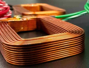
Transformer windings are usually made from copper or aluminum. Copper is preferred because it has excellent electrical conductivity and allows for a more compact winding design. It’s strong, reliable, and handles higher loads well. Aluminum, on the other hand, is lighter and more affordable, making it a good choice when cost or weight is a concern.
But no material is perfect. As current flows through the windings, some energy is lost as heat. This is known as copper loss, or I²R loss, which comes from the resistance of the winding material itself. Another source of energy loss is leakage flux—magnetic energy that escapes the core instead of linking the windings.
Both types of losses reduce the transformer’s overall efficiency, so careful design and material choice are key to getting the best performance.
Conclusion

Transformer winding is the heart of how transformers work—converting voltage levels safely and efficiently using copper or aluminum coils. Understanding the types, layouts, and materials helps you choose or design the right transformer for your needs.
Have questions or need help selecting a winding type? Contact our team today for expert guidance, custom solutions, or more details on transformer winding options.
FAQs About Transformer Winding
1. Why are transformer windings insulated?
Insulation prevents short circuits between turns and layers of wire. It also protects against voltage spikes, heat, and moisture, helping extend the transformer’s life and safety.
2. What causes transformer winding failure?
Common causes include overheating, insulation breakdown, short circuits, mechanical stress, and moisture. Regular testing and proper cooling can help prevent early failure.
3. How is winding resistance measured?
Winding resistance is tested using a low-resistance ohmmeter (DLRO). It helps detect issues like loose connections, shorted turns, or damaged conductors before bigger problems occur.