


Для high-frequency transformers, especially those operating above 50 kHz, способ проектирования обмоток plays a critical role in overall performance. At higher frequencies, conventional design approaches become less effective because the обмотка трансформатора layout directly influences power losses, heat generation, electromagnetic interference, and overall efficiency.
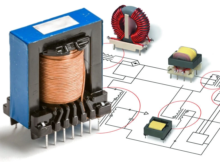
Эффективный обмотка трансформатора design helps reduce Сопротивление переменному току, control эффекты кожи и близости, minimize индуктивность рассеяния, и сохранить электромагнитная интерференция (ЭМИ) within acceptable limits. Whether the application involves a compact SMPS or a custom power module, properly designed обмотки трансформатора are essential for reliable performance, long service life, and compliance with electrical requirements.
In this article, we’ll cover the key winding considerations for high-frequency трансформаторы, using practical design principles and clear explanations to help engineers better understand the factors that affect efficiency and performance.
Эффекты кожи и близости
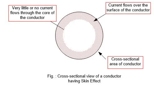
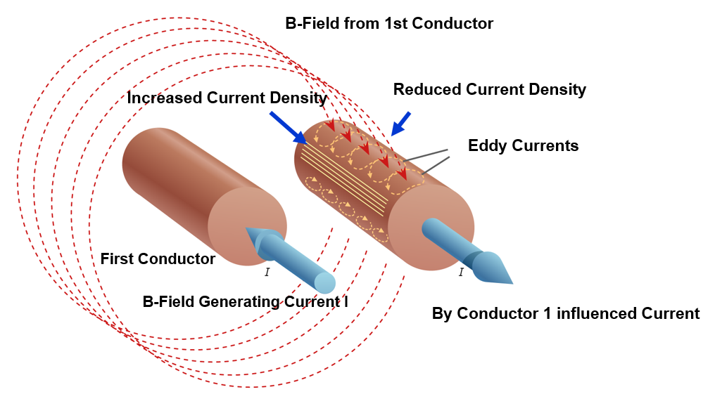
At high frequencies, current no longer flows evenly through the conductor. Instead, it becomes concentrated near the wire surface, a phenomenon known as the скин-эффект. As frequency rises, the effective current-carrying area decreases, increasing Сопротивление переменному току and generating more heat within the обмотка трансформатора.
Next comes the эффект близости. When conductors are positioned close together, their magnetic fields alter the current distribution and force it into narrower paths. This further increases Сопротивление переменному току and reduces обмотка трансформатора эффективность.
Combined with the skin effect, the proximity effect becomes a major source of winding loss in high-frequency transformers. For this reason, selecting the right wire type and winding layout is essential for reducing losses and improving overall performance.
Выбор типа и размера провода

Выбор правильного типа провода is essential for reducing losses in high-frequency обмотки трансформатора.
Среди доступных вариантов, Литцендрат is widely used because it consists of many thin, individually insulated strands woven together to distribute current more evenly. This design helps reduce both кожа и эффекты близости, making it especially effective in high-frequency applications up to about 1 MHz.
However, Литцендрат has practical limits. Above about 1 MHz, strand diameter becomes increasingly important. To remain effective, each strand should generally be менее чем в два раза превышает глубину скин-слоя at the target operating frequency.
For very high frequencies or higher-current обмотка трансформатора applications, alternatives such as обмотки из фольги, трубчатые проводники, и кабели Roebel may provide better current handling while improving magnetic field distribution and thermal performance.
Ultimately, the best conductor depends on the operating frequency, current level, and winding geometry, but the goal remains the same: reduce losses and improve the efficiency of обмотки трансформатора.
Топологии намотки для уменьшения потерь
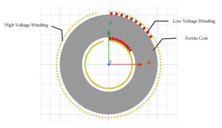
The arrangement of обмотки трансформатора has a significant impact on overall performance. An optimized winding layout can help reduce Сопротивление переменному току, предел parasitic effects, and improve heat management.
Например, paralleled and interleaved windings distribute current more evenly and help reduce the proximity effect. By alternating primary and secondary winding layers, magnetic coupling is improved, which can lower losses and increase efficiency.
Корзиночная (или рассеваемая) обмотка separates conductors rather than placing them closely side by side. This layout helps reduce parasitic capacitance and proximity-effect losses, making it useful in high-frequency обмотка трансформатора designs.
Similarly, sandwich and helical structures can improve current distribution and maintain a more balanced magnetic field. This helps reduce leakage flux and improve the efficiency of обмотки трансформатора.
Each winding layout involves trade-offs, but a well-designed topology can significantly reduce electrical losses and improve overall transformer performance.
Управление паразитами и утечками
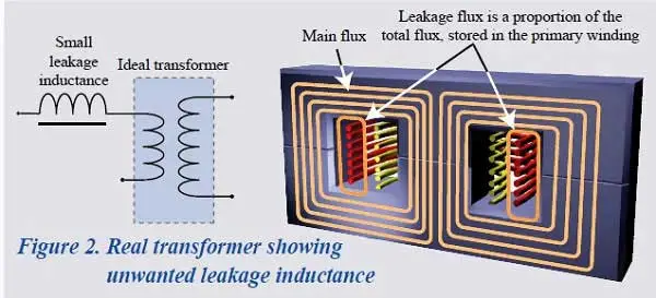
High-frequency transformers commonly face two winding-related challenges: индуктивность рассеяния и паразитная емкость. If not properly controlled, both can reduce the performance and efficiency of обмотки трансформатора.
Индуктивность рассеяния occurs when part of the magnetic flux does not link the primary and secondary windings. While some designs use it intentionally, excessive leakage inductance can slow switching performance and create voltage spikes. Techniques such as interleaved windings и слои утечки can help balance magnetic coupling, insulation, and overall обмотка трансформатора производительность.
Паразитная емкость develops between closely spaced winding layers and can contribute to саморезонанс and EMI problems in high-frequency transformers. Using тщательное соблюдение интервалов между слоями, suitable insulation, and схемы намотки корзин can help reduce this unwanted effect.
Managing these parasitic effects requires a balanced обмотка трансформатора design that limits electrical losses and interference without compromising efficiency, insulation performance, or safety.
Коэффициент изоляции и заполнения

A well-designed обмотка трансформатора layout must balance electrical performance, available space, and safety. The коэффициент заполнения indicates how efficiently the wire occupies the winding window, with higher values allowing more conductor to fit within the same space.
In comparison, ортоциклическая обмотка arranges wires in a uniform pattern and can achieve a fill factor of up to 90%, пока случайная обмотка typically reaches around 75%. A higher fill factor generally means more copper and less unused space, helping improve the efficiency and compactness of обмотки трансформатора.
As winding density increases, изоляция becomes even more important. Proper слой изоляции и диэлектрическое расстояние are essential for preventing short circuits, particularly in high-voltage обмотка трансформатора designs. The choice of insulation material, thickness, and placement all affect long-term safety and reliability.
A well-designed обмотка трансформатора should therefore balance high copper utilization with effective insulation, helping maintain both electrical performance and dependable protection.
Тепловые и механические ограничения
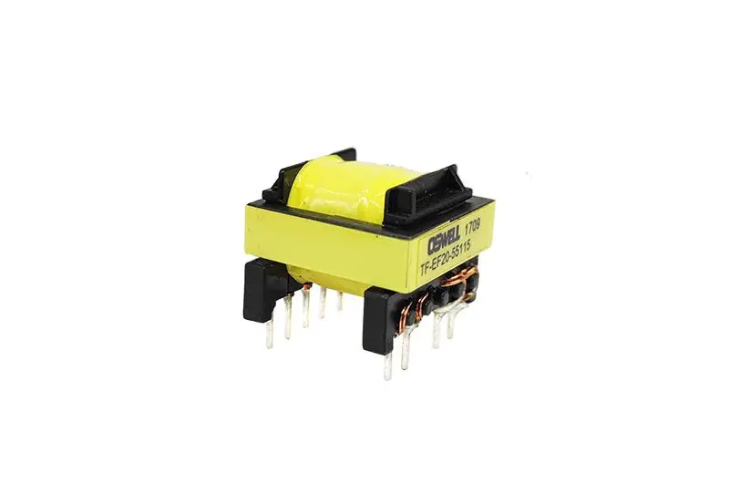 High-frequency transformers can generate significant heat, especially when плотность тока becomes too high. To reduce the risk of overheating, current density should generally remain within a safe range of about 4–10 А/мм², depending on the cooling method and overall обмотка трансформатора дизайн.
In addition, effective охлаждение through airflow, heatsinks, or proper spacing helps control winding temperature, maintain stable performance, and extend the service life of high-frequency обмотки трансформатора.
Mechanical stability is equally important for reliable обмотка трансформатора performance. Windings must withstand вибрация, тепловое расширение, и справляться со стрессом during operation and assembly. If the windings become loose or shift over time, insulation damage and changes in electrical performance may occur.
For this reason, a robust mechanical design helps keep обмотки трансформатора securely in place, supporting consistent efficiency, long-term reliability, and stable operation under real-world conditions.
Интеграция в рабочий процесс проектирования
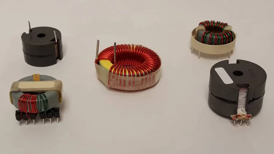
Эффективный обмотка трансформатора design is an итеративный процесс, since each design decision can influence the next. Careful planning is therefore essential for balancing electrical performance, efficiency, and manufacturability.
The process typically begins with выбор ядра based on operating frequency and power requirements, followed by calculating the appropriate количество поворотов for voltage and magnetic flux. Next, the геометрия намотки is refined to balance efficiency, available space, and cooling. Finally, parasitic effects such as leakage inductance and capacitance should be evaluated to ensure stable and reliable обмотка трансформатора производительность.
For better results, конечно-элементный анализ (FEM) tools can be used to evaluate Сопротивление переменному току, плотность тока, распределение магнитного поля, and other key parameters. This helps identify potential обмотка трансформатора issues before moving to the prototype stage.
In practice, effective обмотка трансформатора design combines engineering analysis with practical experience. Integrating these steps early can reduce development time, lower costs, and minimize troubleshooting later.
Передовые практики и новые тенденции
As high-frequency applications continue to advance, обмотка трансформатора techniques are also evolving, with new conductor designs and winding layouts helping improve efficiency and power density.
One example is кабели Roebel, which use transposed strands to reduce Потери переменного тока in strong parallel magnetic fields. This makes them well suited for high-current or compact обмотка трансформатора applications where efficient current distribution is essential.
Спиральные и композитные фольгированные обмотки are also becoming more common in advanced обмотка трансформатора designs. These structures help improve magnetic field uniformity, reduce hotspots, and support more consistent performance at higher operating frequencies.
Another important consideration is циркулирующие токи in parallel strands, which can create additional heat and current imbalance. Proper strand transposition and spacing can help reduce these unwanted effects.
Although these techniques are not required for every design, they can provide clear benefits in efficiency, thermal stability, and EMI control for demanding high-frequency обмотки трансформатора.
Заключение
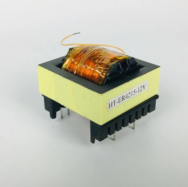
High-frequency transformer performance depends greatly on effective обмотка трансформатора design. From conductor selection and winding geometry to parasitic effects, each factor can influence efficiency, thermal behavior, and long-term reliability. Applying the right design principles helps reduce losses and maintain stable transformer performance.
For support with your обмотка трансформатора дизайн, Свяжитесь с нашей командой for expert guidance, custom solutions, and simulation insights tailored to your specific application.
Часто задаваемые вопросы о намотке высокочастотного трансформатора
1. Какой диапазон частот является идеальным для использования литцендрата?
Литцендрат is generally most effective between 10 kHz and 1 MHz, where skin and proximity effects become more significant. Above 1 MHz, strand diameter and construction must be carefully optimized to control AC losses in high-frequency обмотки трансформатора.
2. Как рассчитать количество витков высокочастотного трансформатора?
A common starting formula for high-frequency обмотка трансформатора design is:
Обороты = (Vin × 10⁸) / (4 × Bmax × Ac × f)
where Vin is the input voltage, Bmax is the maximum flux density, Ac is the core area, and f is the operating frequency. The final turn count may need adjustment for voltage drop and regulation requirements.
3. Можно ли использовать стандартный провод вместо литцендрата для маломощных конструкций?
Yes. For low-current applications operating at relatively low frequencies, standard magnet wire may be suitable for обмотки трансформатора. However, as frequency rises above roughly 100–200 kHz, increasing AC losses should be considered when selecting the conductor.

 Russian
 English
 Spanish
 Italian
 German
 Chinese
Один ответ
Спасибо, что поделились этой содержательной статьей! Я нашел информацию действительно полезной и побуждающей к размышлениям. Ваш стиль письма увлекателен, и он сделал тему намного более понятной. С нетерпением жду новых ваших постов!